Detailed explanation of Roots blower schematic diagram
1、 Basic structure of Roots blower
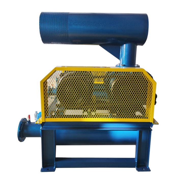
The core components of Roots blower include:
1. Shell: usually made of cast iron material, with precision machining inside
2. Rotor: Two interlocking "8" - shaped impellers
3. Synchronous gear: Ensure the relative position of the two rotors is maintained
4. Bearings: support the operation of the rotor
5. Sealing device: prevent gas leakage
2、 Working principle diagram
1. Inhalation stage: When the rotor rotates, a negative pressure zone is formed on the intake side
2. Transport stage: The gas is enclosed in the space formed by the rotor and the casing
3. Exhaust stage: The rotor continues to rotate, pushing the gas towards the outlet
3、 Key parameter analysis
1. Rotor clearance: usually controlled between 0.1-0.3mm
2. Speed range: generally between 1000-3000rpm
3. Pressure ratio: Single stage can reach 0.98-1.96 kPa
4. Volume efficiency: up to 85 or above
4、 Typical application scenarios
1. Aeration system of sewage treatment plant
2. Pneumatic conveying system
3. Vacuum packaging equipment
4. Gas supply for chemical reaction kettle
5、 Maintenance points
1. Regularly check the gearbox oil level
2. Monitor bearing temperature
3. Clean the intake filter
4. Check the tension of the belt (belt drive type)
Analysis of Roots blower process diagram
1、 System composition
The complete Roots blower system includes:
1. Air intake filter device
2. Muffler
3. Blower host
4. Valve
5. Pressure gauge
6. Export muffler
2、 Gas flow path
1. Atmosphere → intake filter → intake muffler → blower → exhaust pipe → exhaust muffler → gas equipment
3、 Control system process
1. Start sequence: Open the bypass valve → Start the motor → Gradually close the bypass valve
2. Shutdown sequence: Open bypass valve → Stop motor
3. Protection system: Overpressure protection, overload protection, temperature protection
4、 Performance curve analysis
1. Flow pressure curve
2. Power pressure curve
3. Efficiency pressure curve
4. Noise speed curve
5、 Installation precautions
1. Basic requirements: The concrete foundation must be sufficiently stable
2. Pipeline connection: avoid stress caused by forced connection
3. Electrical wiring: meets explosion-proof requirements (special occasions)
4. Debugging steps: no-load trial run → loaded trial run