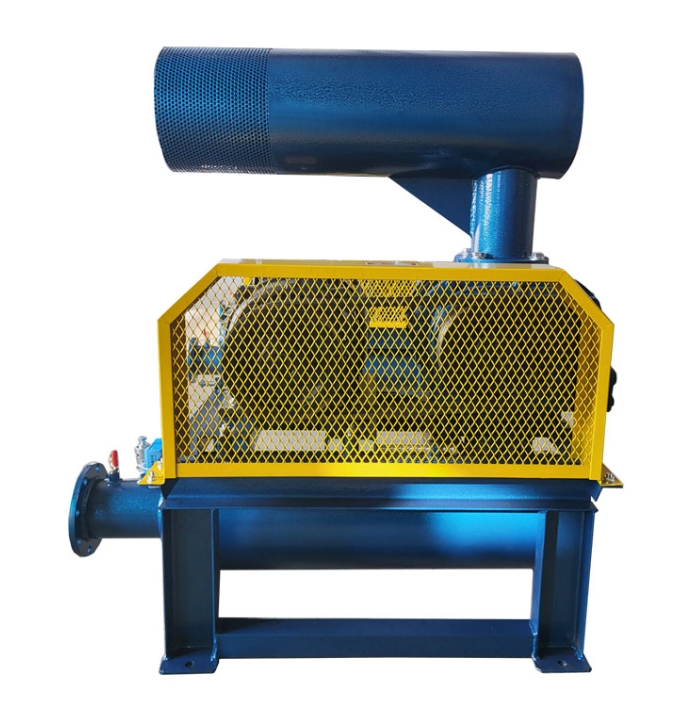
**Analysis of the impact of lengthening the inlet muffler of Roots blower**
**1. The core impact of extending the muffler**
|* * Impact Dimension * * | * * Positive Effect * * | * * Potential Risk * * | * * Critical Threshold * *|
|--------------------|--------------------------------------|---------------------------------------|--------------------------|
|* * Noise reduction performance * * | Low frequency noise reduction improved by 5-8dB | High frequency noise reduction effect may decrease | Reverse effect when aspect ratio>5:1|
|* * Airflow organization * * | Airflow is smoother (Reynolds number decreases) | Dust accumulation may occur when flow velocity<6m/s | Cross section wind speed ≥ 4m/s|
|* * Pressure loss * * | Initial pressure drop reduced by 10-15% | Faster pressure rise after blockage (reduced dust holding capacity) | Strong support required for lengths>2m|
|* * Maintenance convenience * * | Can be designed with segmented inspection ports | Increased difficulty of disassembly and assembly | Flange connections are required every 1.5m|
**2. Variation law of acoustic characteristics**
```mermaid
graph LR
A [Silencer length] -->B [Low frequency cutoff frequency]
A -->C [Transmission loss]
B -->| For every 1m increase | D [lower limit frequency ↓ 15Hz]
C -->| 0.5-2m interval | E [TL=0.5dB/cm]
C -->|>2m | F [TL attenuates to 0.2dB/cm]
```
**3. Suggestions for dynamic simulation**
-Key points of CFD optimization:
-Uniformity of velocity field (velocity standard deviation<15)
-Vortex zone control (turbulence energy<0.1m2/s2)
-* * Typical improvement plan * *:
-Install a guide cone (cone angle of 30 °) when the aspect ratio is 3:1
-Install resistance expansion chambers every 1m (volume ratio 1:1.5)
**4. Structural strengthening scheme**
|* * Extended scope * * | * * Strengthening measures * * | * * Material incremental cost * *|
|----------------|-----------------------------------|----------------|
|1-1.5m | Circular reinforcement bars (spacing 400mm) |+8|
|1.5-3m | Composite sandwich structure (inner and outer panels+truss) |+15|
|>3m | External support frame (carbon steel skeleton) |+25|
**5. Engineering application data**
-* * Sewage treatment plant case * *:
-The 2m long muffler reduces 2.1dBA (63Hz frequency band) compared to the standard model
-The maintenance cycle has been shortened to 4 months (originally 6 months)
-Comparison of Cement Industry:
-Initial pressure drop of 1.8m long muffler 180Pa (standard type 220Pa)
-But after 2 months of use, the pressure difference reached 650Pa (standard type 450Pa)
**6. Selection decision matrix**
```python
DEF muffler selection (flow rate, noise spectrum, space limitations):
If the noise spectrum [low frequency ratio] is greater than 40 and spatial constraints==False:
Return "Extended type (1.5-2m)"
Elif flow rate>50m3/min and noise spectrum [high-frequency prominent]:
Return "Standard type+Level 2 noise reduction"
else:
Return "Standard Type (1m)
```
**7. Response to special working conditions**
-High humidity environment:
-Extension requires a 45 ° drainage slope (with a drop of 3cm per meter)
-Spray polyurea anti-corrosion coating on the inner wall (thickness ≥ 2mm)
-Pulsating airflow:
-For every 1m increase in length, an additional Helmholtz resonator (with a volume of 5L) needs to be added
**8. Economic analysis**
-Cost benefit ratio:
-For every 0.5m increase in length, the price of the muffler increases by 12
-But the noise reduction benefits decrease (only 1-2dB increase per meter after>2m)
-* * Investment payback period * *:
-When meeting noise standards: 2-3 years for regular use
-Special mute requirement: may be extended to 5 years
**Suggestion: When it is necessary to focus on controlling low-frequency noise at 63-250Hz and the installation space allows, a 1.5-2m extended muffler can be used; For conventional applications, the standard model (0.8-1.2m) is still a cost-effective option. The extended design must be equipped with a differential pressure monitoring system, and it is recommended to set an automatic alarm value of 800Pa.


