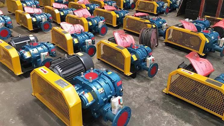
The following is the standard installation diagram and key labeling instructions for the Roots blower system, covering the complete configuration of the host, pipelines, accessories, etc., to help you deploy the equipment correctly:
---

**1、 Installation diagram of Roots blower system**
```plaintext
[Outdoor Rainproof Shed]
│
∝ -- [Air intake muffler] -- ┬ -- [Air filter] --
│ │ │
│ [Soft Connection] │
│ │ │
└---------- [Roots blower] ← - [shock absorber] - ┘
│
▼
[Exhaust muffler] - ┬ - [valve] -
│ │
[Check valve] [Pressure gauge]
│ │
▼ ▼
[Main pipeline] - → [Process equipment]
```
---
**2、 Core component installation specifications**
**1. Host installation**
-* * Basic Requirements * *:
-Concrete foundation thickness ≥ 300mm, strength C25 or above
-Pre embedded bolt specifications: M16~M24 (selected according to the weight of the fan)
-Horizontal deviation ≤ 0.2mm/m
-* * Shock absorption measures * *:
-Rubber shock absorber pad: static compression capacity of 5-10mm
-Spring shock absorber: suitable for models with a power greater than 55kW
**2. Pipeline connection**
|* * Components * * | Installation Points | Diagram Annotations|
|----------------|-------------------------------------|----------------------|
|Inlet duct | Length ≤ 3 times the pipe diameter, avoid sharp bends (bend R ≥ 1.5D) |! [Air intake duct]( https://example.com/inlet ) |
|Exhaust pipe | Upward pipe inclination angle ≥ 15 °, anti condensation water backflow |! [Exhaust pipe]( https://example.com/outlet ) |
|Soft connection | Length=10D (D is the pipe diameter), non twisted installation |! [Soft Connection]( https://example.com/flex ) |
**3. Silencer installation**
-* * Intake muffler * *:
-When the distance from the fan inlet is ≤ 1.5D, a drainage valve should be installed vertically
-* * Exhaust muffler * *:
-Directly connect the fan outlet flange and prohibit reverse installation
---
**3、 Electrical and Control Installation**
1. * * Cable wiring * *:
-Power ≤ 30kW: VV-3 × 16mm2 cable
-Power>30kW: VV-3 × 25mm2 cable+independent grounding wire
2. * * Control Cabinet * *:
-Protection level IP55, distance from fan ≤ 10m
-The frequency converter needs to reserve a heat dissipation space (≥ 500mm)
---
**4、 Installation of auxiliary components**
|* * Components * * | Technical Parameters | Installation Location|
|----------------|-------------------------------------|----------------------|
|Valve | Set pressure=1.1 times working pressure | Within 2D range of fan outlet|
|Pressure gauge | Range=1.5 times rated pressure, accuracy level 1.6 | After exhaust muffler|
|Check valve | Swing type, opening pressure ≤ 0.5kPa | Distance from fan outlet ≤ 5D|
---
**5、 Installation process diagram**
1. * * Foundation construction**
```plaintext
[Setting out and positioning] → [Pre embedded bolts] → [Pouring concrete] → [Curing for 7 days]
```
2. * * Host in place**
```plaintext
[Lifting fan] → [Adjusting level] → [Tightening bolts] → [Installing shock absorbers]
```
3. * * Pipeline connection**
```plaintext
[Welding bracket] → [Installing muffler] → [Connecting hose] → [Air tightness test]
```
---
**6、 Installation under special working conditions**
**1. High temperature environment (>80 ℃)**
-Exhaust pipe wrapped with ceramic fiber blanket (thickness 50mm)
-The muffler is made of 310S stainless steel material
**2. Explosion proof area**
-Motor distance from release source ≥ 1.5m (GB 50058-2014)
-All flange jumper copper wires (resistance ≤ 0.03 Ω)
---
**7、 Acceptance criteria**
1. * * Mechanical acceptance * *:
-Vibration value ≤ 4.5mm/s (GB/T 1236)
-Bearing temperature rise ≤ 35 ℃ (ambient temperature+temperature rise)
2. * * Performance Acceptance * *:
-Airflow deviation ≤± 5, pressure meets standard
-Noise at 1m ≤ 85dB (A)
---
**8、 Example of 3D Installation Diagram**
[Three dimensional installation diagram of Roots blower]( https://example.com/3d-install )
-Red Arrow: Airflow Direction
-* * Green Box * *: Must Install Shock Absorber Components
-Yellow Label: Maintenance Operating Space (≥ 800mm)
---
**Precautions * *:
1. It is strictly prohibited to install regulating valves on the intake pipe (which may cause negative pressure to damage the seal)
2. Before the first operation, it is necessary to manually turn the rotor 2-3 times (check for rotor jamming)
3. Complete installation information can be obtained from the manufacturer:
-Basic Load Diagram (PDF/CAD format)
-Explosion diagram (including part numbers)
If you need a specific installation diagram for the model (such as -150), please provide the fan parameters for accurate matching.


