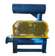
Detailed dissection diagram of Roots blower: in-depth understanding of equipment structure and working principle
The anatomical diagram of Roots blower is an important technical document that displays the internal structure and component composition of the equipment. Through the anatomical diagram, the structural characteristics and working principles of the equipment can be intuitively understood. Mastering the interpretation methods of anatomical diagrams can help users better use and maintain equipment.
Basic composition of anatomical diagram
A complete anatomical diagram of a Roots blower typically includes a cross-sectional view of the entire machine and an exploded view of its components. The overall cross-sectional view displays the internal structure layout of the equipment, clearly showing the positional relationship of core components such as rotors, gears, and bearings. The component breakdown diagram unfolds each component in assembly order, labeling the name and number of each part.
Use standard legends in anatomical diagrams to represent different components. The solid line represents the visible outline, the dashed line shows the hidden part, and the section line distinguishes different materials. Dimensioning is measured in millimeters, and tolerance symbols are used to indicate machining accuracy requirements. The flow arrow indicates the direction of gas movement, and the symbol indicates the workflow.
Core component analysis
The rotor is the most critical component of a Roots blower, and the anatomical diagram clearly shows its blade structure and installation position. The active rotor and the driven rotor are synchronized through gears and rotate in a non-contact reverse direction inside the casing. The design of rotor profile directly affects equipment efficiency, and the anatomical diagram can clearly display its contour features.
The gearbox displays the meshing relationship of synchronous gears. The driving gear is installed on the motor shaft, and the driven gear drives another rotor. The gear accuracy level and heat treatment requirements are clearly marked in the anatomical diagram. The lubricating oil system displays the circulation path of lubricating oil, including the inlet, return hole, and oil passage distribution.
Airflow channel display
The intake system displays the installation positions of the air filter and muffler. The air inlet is usually located on the side of the gearbox and connected to the intake chamber of the casing through a pipeline. The anatomical diagram clearly shows the complete path of gas from the inlet to the rotor working chamber.
The exhaust system includes an exhaust chamber and an exhaust muffler. Gas is pushed by the rotor from the working chamber into the exhaust chamber and discharged through the muffler. The installation positions of exhaust valves and devices are clearly marked in the anatomical diagram for easy daily inspection and maintenance.
Detailed explanation of sealing system
The shaft seal system prevents lubricating oil leakage and gas escape. The anatomical diagram shows the installation position and structural form of seals, including different types of seals such as oil seals and gas seals. The wall panel seal ensures the sealing of the casing end face, preventing gas leakage from the rotor shaft end.
The material selection and installation requirements for seals are indicated in the anatomical diagram. For reinforced sealing structures used in special working conditions, the anatomical diagram will specifically indicate their characteristics and usage precautions.
Supporting system structure
The bearing system supports the operation of the rotor and bears radial and axial loads. The anatomical diagram shows the installation position and fixing method of the bearing, including the bearing seat structure, lubrication channel, etc. The support structure of the base and frame ensures stable operation of the equipment, and the damping device reduces vibration transmission.
The anatomical diagram also shows the connection method of the coupling or belt transmission device, the alignment requirements between the motor and the fan, etc. These pieces of information have important guiding significance for equipment installation and debugging.
Usage and maintenance guidance
Through anatomical diagrams, maintenance plans can be better developed. The lubrication point indicates the regular refueling position, and the inspection point marks the key areas for daily inspection. The disassembly sequence guides the operation steps during major repairs to avoid damage caused by incorrect disassembly.
The part number corresponds to the detailed list for easy procurement and management of spare parts. The installation dimensions and tolerance requirements provide accurate basis for maintenance. These pieces of information greatly improve the standardization and efficiency of equipment maintenance.
In short, the anatomical diagram of Roots blower is an important technical material for understanding the equipment structure and guiding installation and maintenance. Correctly interpreting anatomical diagrams can help users gain a deeper understanding of the working principle of the equipment and improve their level of use and maintenance. It is recommended that users keep the anatomical images properly and make full use of their value in daily work.


