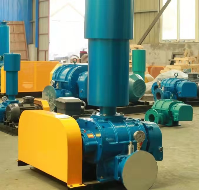
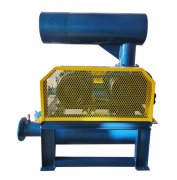
The installation location of the muffler for Roots blower needs to be scientifically configured according to the * * noise control objectives * * and * * system design * *, mainly divided into three types: * * intake muffler * *, * * exhaust muffler * *, and * * bypass muffler * *. The following are detailed installation specifications and technical points for each part:
---

**1、 Core installation location of muffler**
**1. Inlet silencer (imported silencer)**
-* * Installation location * *:
-Between the fan inlet and the air filter (if the filter is installed before, it is installed after the filter).
-Distance from the inlet of the fan: ≤ 1.5 times the diameter of the pipe (to prevent airflow regeneration noise).
-* * Structural Features * *:
-Resistance silencing is the main approach (expansion chamber+resonant cavity) to reduce low-frequency noise (63-500Hz).
-Integrated filter screen (stainless steel wire mesh, aperture 1-3mm).
-* * Typical parameters * *:
-Noise reduction level: 15-20dB (A)
-Pressure loss: ≤ 150Pa
**2. Exhaust silencer (outlet silencer)**
-* * Installation location * *:
-Between the fan outlet and the pipeline system, adjacent to the fan outlet flange (distance ≤ 1 pipe diameter).
-If long-distance transportation is required, a secondary muffler should be installed in the middle section of the pipeline.
-* * Structural Features * *:
-Composite design (resistive sound absorption+resistance expansion), covering all frequency bands of noise.
-Pressure resistant design (≥ 1.1 times the rated pressure of the fan).
-* * Typical parameters * *:
-Noise reduction level: 20-30dB (A)
-Pressure loss: ≤ 2kPa
**3. Bypass silencer (valve silencer)**
-* * Installation location * *:
-On the discharge pipeline of the valve or pressure relief valve.
-Vertical installation, with the discharge port facing upwards (to prevent rainwater intrusion).
-* * Structural Features * *:
-Small hole injection muffler, designed for transient noise caused by high-pressure airflow.
-The material should be impact resistant (cast steel or stainless steel).
-* * Typical parameters * *:
-Noise reduction level: 10-15dB (A)
-Discharge back pressure: ≤ 5 times the valve opening pressure
---
**2、 Installation technical specifications**
**1. Pipeline connection requirements**
|* * Project * * | Inlet Muffler | Exhaust Muffler|
|------------------|------------------------|------------------------|
|* * Flange Standard * * | PN10/DN Series | PN16/ANSI 150|
|Sealing material * * | Rubber gasket (oil resistant) | Graphite metal winding gasket|
|* * Support method * * | Independent bracket (anti gravity transmission) | Rigid support+shock absorber|
**2. Flow direction and drainage design**
-* * Airflow direction * *:
-It must be aligned with the direction indicated on the muffler (reverse installation increases pressure loss by 3-5 times).
-* * Drainage Configuration * *:
-A DN20 drain valve is installed at the bottom of the exhaust muffler to treat condensed water.
-When installing at an angle, the slope should be ≥ 5 ° (natural drainage).
**3. Spacing**
-Distance between muffler and wall: ≥ 300mm (for easy maintenance).
-When multiple units are connected in parallel, the spacing between mufflers should be ≥ 1 time the length of the muffler.
---
**3、 Installation plan for special working conditions**
**1. High temperature gas (>120 ℃)**
-The muffler casing has been replaced with 310S stainless steel.
-Install expansion joints to compensate for thermal expansion (compensation amount ≥ 5mm/m).
**2. Corrosive medium**
-Full PP/PVDF material muffler.
-Add anti-corrosion lining at the flange connection.
**3. Explosion proof area**
-The muffler shell is grounded (resistance ≤ 4 Ω).
-Anti static rock wool is selected as the sound-absorbing material.
---
**4、 Installation effect verification**
1. * * Noise detection * *:
-According to GB/T 3768 standard, measure at a distance of 1m from the muffler.
-Expected effect: ≤ 85dB (A) after import silencing, ≤ 80dB (A) after export silencing.
2. * * Pressure loss test * *:
-The U-shaped differential pressure gauge measures the pressure difference before and after the muffler, which should be less than 10% of the rated value.
---
**5、 Common installation errors and corrections**
|* * Problem * * | * * Consequence * * | * * Solution * *|
|------------------|--------------------------|-------------------------|
|Silencer reverse installation | Sudden increase in pressure loss, noise reduction failure | Check the airflow direction arrow|
|No drainage valve installed | Soaked sound-absorbing cotton reduces lifespan by 50 | Automatic water trap installed|
|Lack of soft connection | Vibration transmission to pipeline | Installation of rubber soft joint (length ≥ 10D)|
---
**6、 Maintain interface design**
1. * * Maintenance port * *:
-Set up a 200mm quick opening manhole on the side for replacing sound-absorbing materials.
2. * * Pressure tap * *:
-Reserve 1/4 "NPT interface (for connecting differential pressure gauge).
3. * * Hanging ear * *:
-Load capacity ≥ 2 times the weight of the muffler (easy to replace).
---
**Summary * *:
-Practice: The combination of intake muffler and exhaust muffler can achieve a total noise reduction of 35-45dB (A).
-* * Pit Avoidance Guide * *: It is strictly prohibited to use exhaust silencers on the intake end (due to insufficient structural pressure resistance, they are prone to bursting).
-Customization suggestion: For non-standard working conditions (such as dust content>50mg/m3), it is necessary to customize a cyclone dust removal and silencing integrated machine.
Before installation, it is necessary to consult the installation manual provided by the fan manufacturer for the muffler, and prioritize using the original matching muffler to ensure performance matching.


