
**Detailed explanation of installation steps for Roots blower (Professional Engineer Edition)**
---
**1、 Preparation before installation**
1. * * Basic acceptance**
-Concrete strength ≥ C25, flatness deviation ≤ 2mm/m2
-Position error of pre embedded anchor bolts ± 3mm (it is recommended to use elastic shock-absorbing pads)
-Reserved maintenance space: ≥ 800mm on both sides, ≥ 1000mm on the top
2. * * Unpacking inspection**
-Check the nameplate parameters (flow rate/pressure/speed)
-Check the flexibility of rotor rotation (no jamming during manual turning)
-Confirm that the attachments are complete (couplings, anchor bolts, instructions, etc.)
---
**2、 Mechanical installation process**
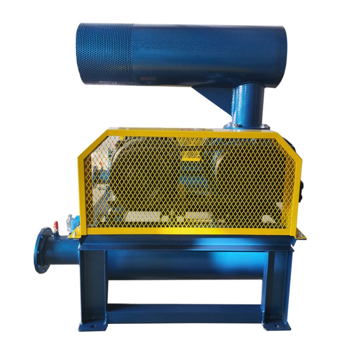
1. * * Host in place**
-Use forklifts or lifting equipment (with lifting points located on dedicated lifting lugs)
-After initial leveling, the anchor bolts are temporarily not tightened (leaving a 0.5mm adjustment allowance)
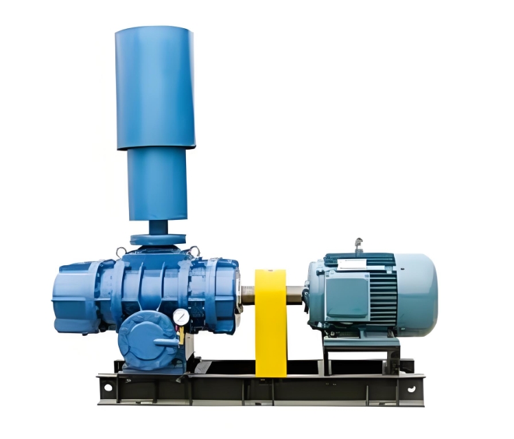
2. * * Horizontal calibration**
-Measure on the machined surface of the bearing seat, with a levelness of ≤ 0.05mm/m
-Use a precision level (accuracy 0.02mm/m)
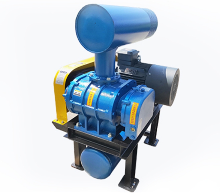
3. * * Coupling/Belt Installation**
|* * Transmission type * * | * * Technical requirements * *|
|--------------|------------------------------|
|Direct connection | Radial deviation ≤ 0.05mm, angular deviation ≤ 0.02mm|
|Belt drive | Belt tension: press down with thumb to sink 10-15mm|
4. * * Import and export pipeline connection**
-Add asbestos rubber pad (thickness 3mm) between flanges
-The pipeline needs to be independently supported (fan bearing is prohibited)
-The distance between the elbow and the inlet is ≥ 2 times the pipe diameter (to reduce turbulence)
---
**3、 Key points of electrical installation**
1. * * Motor wiring**
-380V three-phase motor insulation resistance ≥ 1M Ω (tested with a 500V megohmmeter)
-Steering confirmation: jog test consistent with the arrow on the shell
2. * * Control System**
-Variable frequency drive parameter setting (startup time ≥ 30 seconds)
-The overload protection value is set to the rated current of 110
---
**4、 Installation of auxiliary systems**
1. Lubrication system**
-Inject ISO VG220 gear oil into the gearbox to the centerline of the oil gauge
-The bearings are lubricated with lithium grease (with a grease injection volume of 60% of the cavity)
2. * * Cooling system**
-Water cooled machine model pressure test 0.4MPa, hold for 30 minutes without leakage
-Air cooled models ensure unobstructed heat dissipation fins
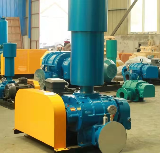
3. * * Device**
-Valve popping pressure ≤ 1.1 times rated pressure
-The range of the pressure sensor covers 1.5 times the working pressure
---
**5、 Debugging and running steps**
1. * * No load test run**
-Remove the coupling/belt and test the motor for 30 minutes
-Test vibration value (≤ 4.5mm/s at the bearing)
2. * * Load trial operation**
|* * Stage * * | * * Operational Requirements * * | * * Acceptance Criteria * *|
|------------|------------------------------|-------------------------|
|0-30 minutes | 25 load operation | Bearing temperature rise ≤ 40 ℃/h|
|30-60 minutes | 50 load operation | Current fluctuation ≤ 5 rated value|
|1-2 hours | Load operation | No leakage at each flange interface|
3. * * Performance testing**
-Flow deviation ≤± 5 (detected by orifice flowmeter)
-Noise test (≤ 85dB (A) at a distance of 1m from the equipment)
---
**6、 List of Acceptance Documents**
1. Observation records of foundation settlement (continuous for 7 days)
2. Vibration detection report (including spectrum analysis)
3. Trial operation data record table (hourly record)
4. Lubricating oil testing report (particle size NAS level 8)
---
**7、 Professional precautions**
1. Explosion proof places**
-Use copper tools (to avoid sparks)
-The junction box must comply with the Ex d Ⅱ CT4 standard
2. High temperature medium**
-Expansion joints are installed in the import and export pipelines (compensation amount ≥ 5mm)
-At least 3 temperature measurement points on the shell (top/sides)
3. * * Special materials**
-Stainless steel fans need to be pickled and passivated after welding
-Titanium alloy rotors are prohibited from coming into contact with chlorine containing cleaning agents
---
**Attachment: Installation Deviation Control Table**
|* * Project * * | * * Allowable Deviation * * | * * Testing Tool * *|
|----------------|----------------|-------------------|
|Levelness | ≤ 0.05mm/m | Electronic level|
|Coupling alignment | ≤ 0.03mm | dial gauge+alignment frame|
|Pipeline stress | ≤ 0.1mm/m | Laser collimator|
According to this specification, installation can ensure that the operating life of the equipment is ≥ 10 years, and the first major overhaul cycle is extended by 30 years. Suggest saving the installation process image data for future reference.