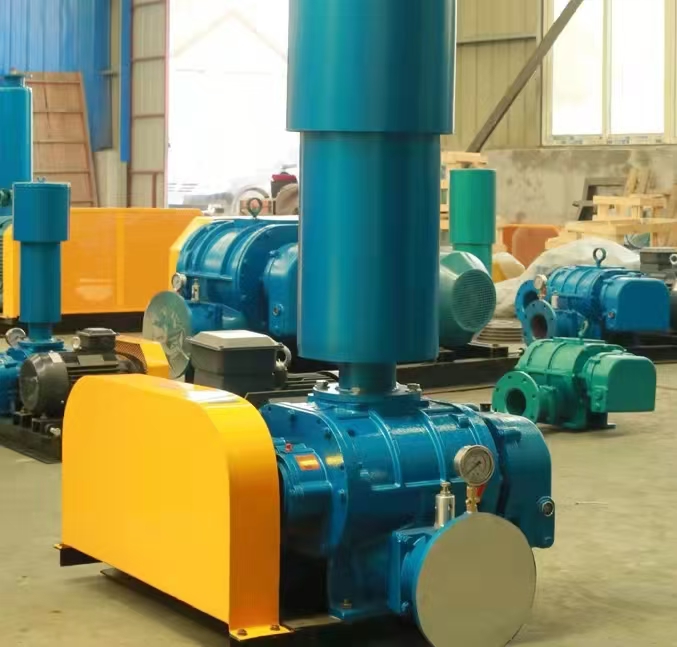
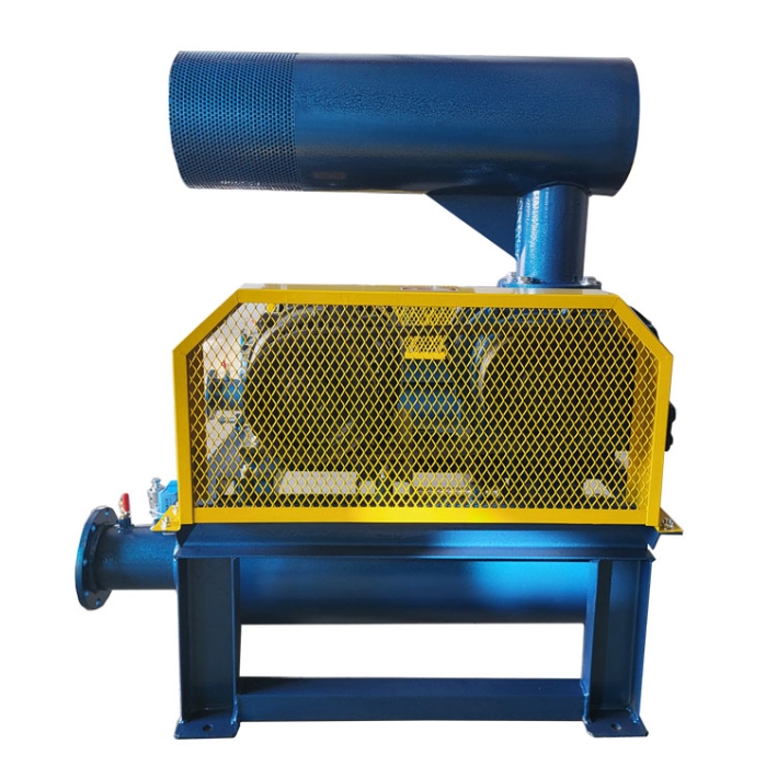
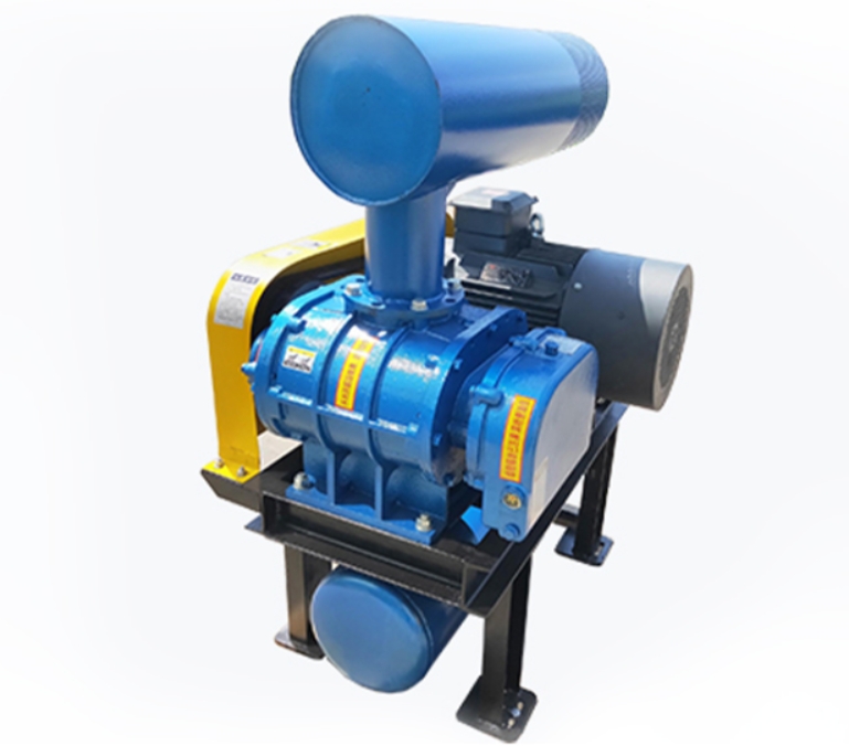
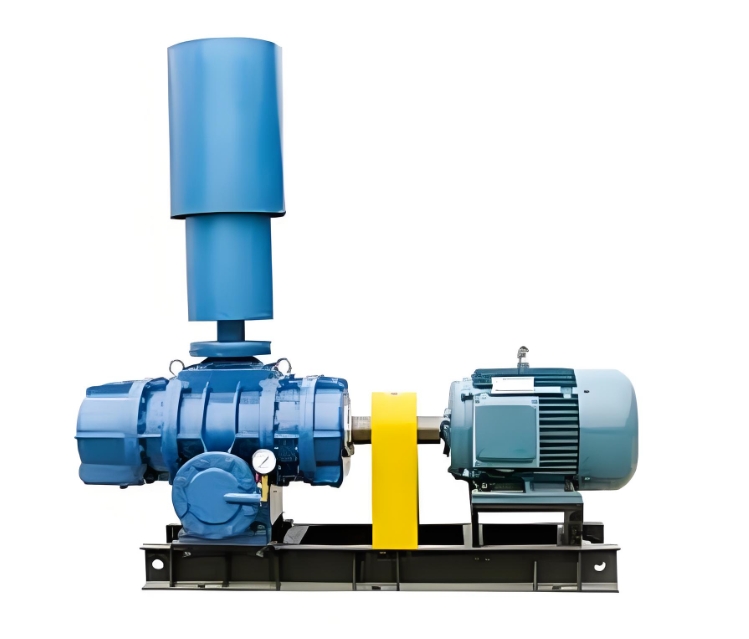
The following is a typical internal structure diagram and key component analysis of the Roots blower muffler, to help you intuitively understand its noise reduction principle:
---

**1、 Schematic diagram of the internal structure of the muffler**
```
[Inlet flange]
│
∝ -- Airflow direction
│
│ +-------------------------------+
│ | ████████████████████ | ← Shell (carbon steel/stainless steel)
│ | █ [Expansion chamber] [Sound absorbing layer] █|
│ | █ ┌──────┐ ┌─────┐ █ |
│ | █ │ Blocking plate │ │ Perforated plate │█ | ← Resistance silencing unit
│ | █ └──────┘ ├─────┤ █ |
│ | █ │ Glass wool │█ | ← Resistive silencing unit
│ | █ └─────┘ █ |
│ | ████████████████████████████ |
│ | |
│ +-------------------------------+
│
│▲ Drainage valve (bottom)
│
[Gas outlet flange]
```
---
**2、 Detailed explanation of core components**
**1. Resistance silencing unit (expansion chamber type)**
-* * Function * *: Reflecting low-frequency noise (63-500Hz) through cross-sectional abrupt changes
-* * Structure * *:
-Barrier spacing=1/4 target wavelength (such as approximately 680mm spacing for 125Hz noise)
-The expansion ratio (cross-sectional change ratio) is usually 3:1~5:1
**2. Resistive silencing unit (sound-absorbing layer)**
-* * Composition * *:
-Perforated Plate: 1.5mm thick galvanized steel plate with a diameter of 5mm and a perforation rate of 25
-* * Sound absorbing material * *: Ultra fine glass wool (thickness 50-100mm, density 48kg/m3)
-* * Noise reduction frequency band * *: 500-4000Hz medium high frequency noise
**3. Airflow channel design**
-Flow rate control: Channel cross-sectional area ≥ 1.2 times the inlet pipe cross-sectional area (maintaining flow rate<15m/s)
-* * Guide plate * *: V-shaped guide structure reduces vortex regeneration noise
---
**3、 Key Annotations for 3D Sectional View**
```plaintext
[Flange connection]
│
▼
┌───────────────────────┐
│▲ Airflow guide cone │
││ (Reduce inlet turbulence) │
│ ├─────────────────┤
││ Expansion chamber │→ Reflects low-frequency sound waves
││ (section mutation zone) │
│ ├─────────────────┤
││ Sound absorbing cotton+perforated board │→ Absorbs mid to high frequency sound waves
││ (Multi layer staggered arrangement) │
│ ├─────────────────┤
│▼ Drainage chute │→ Slope ≥ 5 °
└───────────────────────┘
```
---
**4、 Comparison of different structural types**
|* * Type * * | * * Structural Features * * | * * Noise Reduction * * | * * Pressure Loss * * | Applicable Scenarios|
|----------------|---------------------------|-------------|------------|---------------------|
|Expansion chamber type | Multi chamber section mutation | 15-20dB (A) | 1.5-3kPa | Low frequency noise is predominant (<500Hz)|
|Maze style * * | Curved baffle extension path | 25-30dB (A) | 3-5 kPa | Broadband noise (requires high noise reduction)|
|* * Composite * * | Expansion chamber+sound-absorbing layer combination | 20-25dB (A) | 1-2kPa | Most Roots blowers|
---
**5、 Key points of selection design**
1. * * Noise spectrum matching**
-Measure the peak frequency of fan noise (if 250Hz is the main frequency, the expansion chamber needs to be strengthened).
2. Pressure loss control**
-Total pressure loss ≤ 10% of the allowable back pressure of the fan (for example, a muffler with Δ P < 9.8kPa should be selected for a 98kPa fan).
3. Anti corrosion requirements**
-Corrosive gas environment requires the use of:
-Stainless steel casing (304/316L)
-PTFE coated sound-absorbing cotton
---
**6、 Maintain entrance design**
-* * Maintenance port * *: A detachable cover plate with a diameter of 200mm is installed on the side (for easy replacement of sound-absorbing materials)
-* * Quick detection * *: Reserved noise detection hole (with threaded sealing cover)
---
For more detailed engineering drawings (such as CAD/SolidWorks format), it is recommended to contact the muffler manufacturer to provide model specific structural drawings, or refer to the following standards:
-GB/T 4760-1995 * "Measurement Methods for Air Mufflers"
-JB/T 6891-2010 Technical Conditions for Mufflers for Fans


