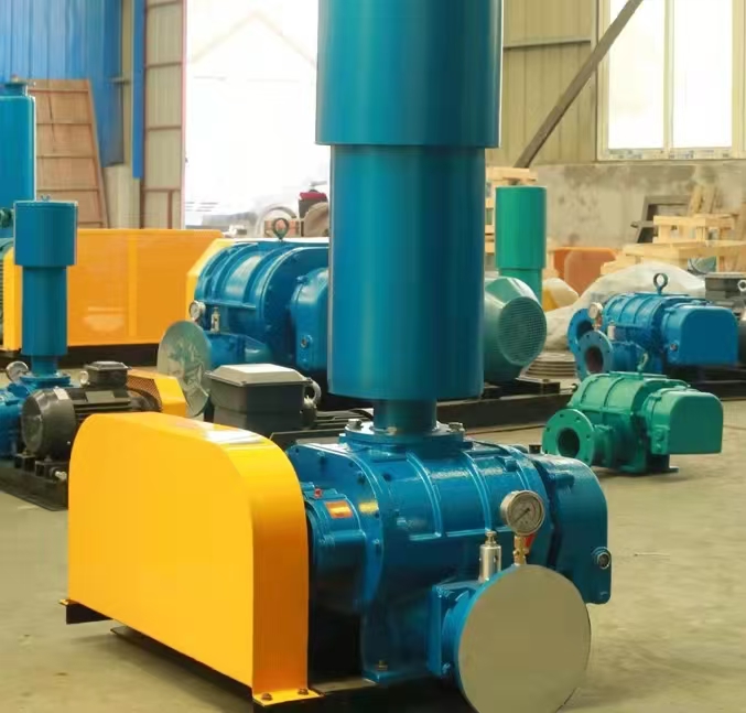
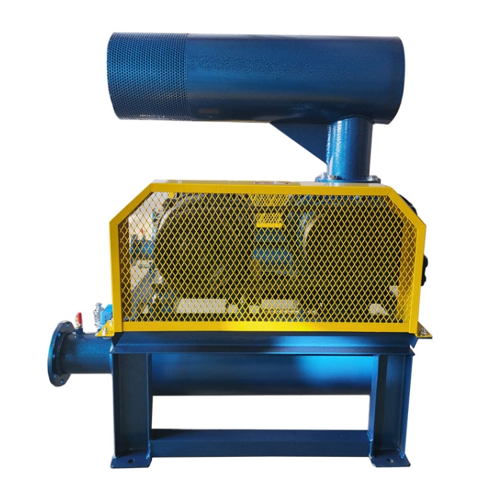
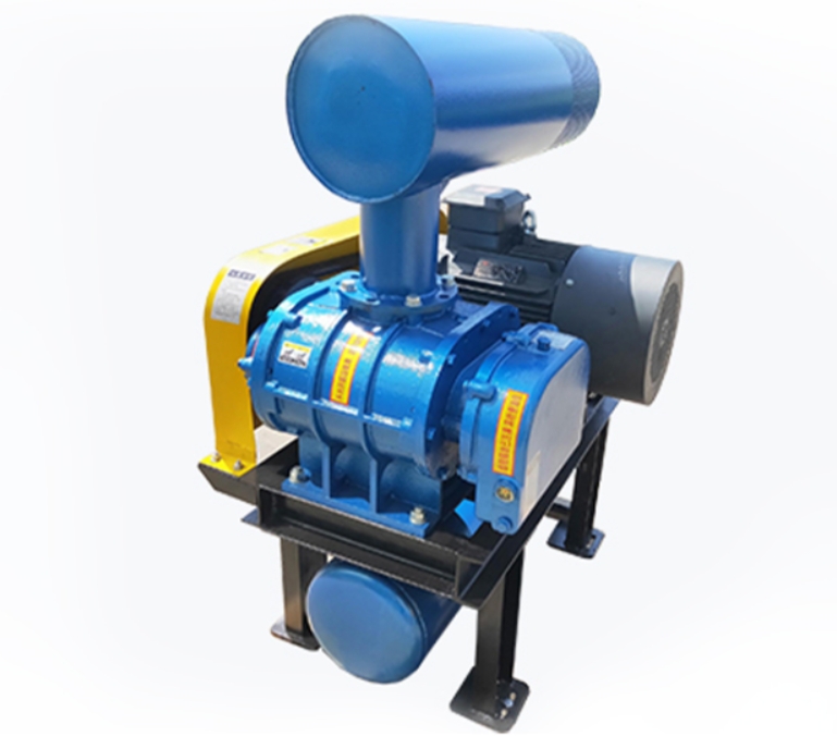
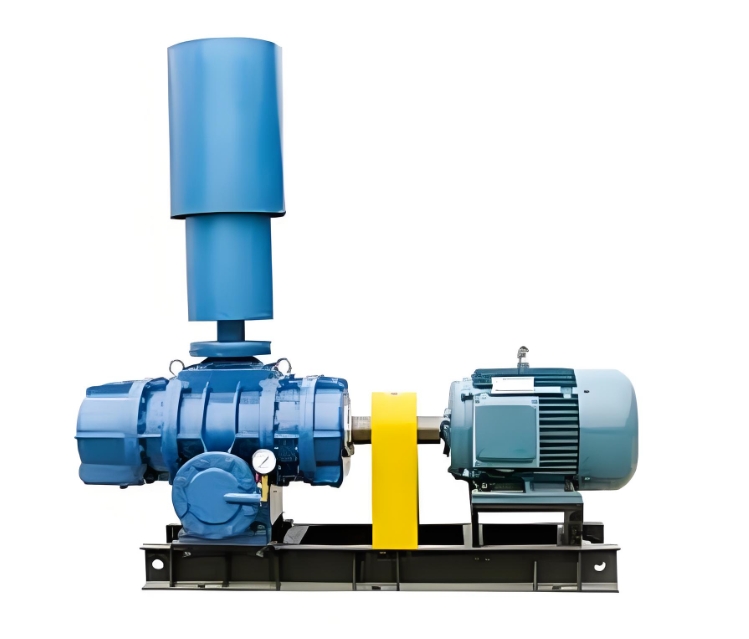
Boiler Roots blower is a type of positive displacement fan, mainly used to deliver combustion air (primary or secondary air) to the boiler or provide flue gas circulation power. Its working principle is based on forced gas delivery between rotors, as follows:
---

**1. Core structure**
-* * A pair of synchronous gear driven rotors * *: usually two or three bladed, with gaps (about 0.1-0.4mm) between rotors and between rotors and shells, but without direct contact.
-Inlet and outlet: Gas is drawn in from one side and forced out from the other side, with the direction determined by the rotation of the rotor.
-Shell: A sealed space accommodates the rotor to ensure that gas does not reflux.
---
**2. Working process**
1. * * Inhalation stage**
-When the rotor rotates, the volume on the intake side gradually increases, creating negative pressure that draws air into the chamber.
-The rotor and shell seal the gas to prevent backflow (as shown in stage ①→② of Figure 1).
2. * * Transportation stage**
-The rotor continues to rotate, and the gas is enclosed in the space between the rotor and the housing, pushing from the intake side to the exhaust side (stages ② → ③).
-* * No internal compression * *: The gas is not compressed in the chamber, and the pressure only comes from the exhaust side resistance.
3. * * Exhaust Stage**
-When the rotor is connected to the exhaust port, gas is forcibly discharged (stages ③ → ④).
-Due to the high pressure on the exhaust side, some gas may flow back through the gap, and the flow rate needs to be maintained by speed and sealing.
! [Working principle diagram of Roots blower]( https://example.com/roots-blower-diagram.png )
(Illustration: Gas delivery process during rotor rotation)
---
**3. Key features**
-Constant flow conveying: The air volume is proportional to the speed, and the pressure depends on the system resistance (up to about 100kPa).
-* * No internal compression * *: The increase in pressure depends on the back pressure on the exhaust side, so the efficiency is lower than that of centrifugal fans (energy consumption is higher at high pressure).
-Pulse airflow: The rotor engagement will generate airflow pulsation, usually requiring the installation of a muffler or buffer tank.
---
**4. Application in boilers**
-* * Combustion air supply * *: Provides stable air flow for the burner to ensure full combustion of fuel.
-Flue Gas Recirculation (FGR): Mixing some flue gas back into the combustion zone to reduce NOx emissions.
-Positive pressure ventilation: Maintain a slight positive pressure in the furnace to prevent cold air from infiltrating.
---
**5. Difference from centrifugal fan**
|* * Features * * | * Roots blower * * | * * Centrifugal blower * *|
|----------------|----------------------------|--------------------------|
|* * Working principle * * | Volumetric (mechanically squeezed gas) | Kinetic (impeller accelerated gas)|
|* * Pressure range * * | Medium high pressure (up to 100kPa) | Low pressure (usually<20kPa)|
|* * Flow regulation * * | Variable frequency speed regulation or bypass valve required | Adjustable through inlet guide vanes|
|* * Efficiency * * | Low (especially at high pressure) | High|
|* * Maintenance * * | Simple structure, but precise clearance requirements | Regular balancing of impellers required|
---
**6. Frequently Asked Questions**
-Overheating: Long term high back pressure operation causes rotor expansion, exacerbating wear.
-* * Noise/Vibration * *: Caused by gear wear or rotor imbalance, requiring regular calibration.
-Insufficient air volume: caused by filter blockage, belt slippage, or increased clearance.
---
**Summary: Roots blower forcibly delivers gas through rotor engagement, suitable for scenarios in boilers that require stable flow and medium to high pressure, but attention should be paid to maintaining clearances and system back pressure.


